Newsletter Subscribe
Enter your email address below and subscribe to our newsletter

 ByJohn A
Renewable energy substations must accommodate changing power flows, inverter-based generation, and demanding electrical protection requirements. Solar photovoltaic plants, wind farms, and battery energy storage facilities all rely on well-designed grounding systems to manage electrical faults and protect critical equipment. Within these installations, a zigzag earthing transformer can provide an essential function: establishing an artificial neutral point on a three-phase network that otherwise lacks a suitable grounding reference.
As renewable energy projects expand in capacity and connect to increasingly complex distribution networks, grounding design deserves attention from the earliest stages of substation engineering. An incorrectly designed grounding arrangement can affect ground-fault detection, insulation performance, and protective relay operation. A properly specified zigzag earthing transformer helps address these challenges by providing a defined zero-sequence current path and supporting a coordinated grounding strategy.
Understanding zigzag earthing transformer applications in renewable energy substation design requires examining how the equipment works, where it is installed, how it interacts with inverter-based resources, and which technical factors determine its suitability for a particular project.
A zigzag earthing transformer is a specialized three-phase transformer designed primarily to establish a neutral point for grounding. Its interconnected winding arrangement provides a relatively low-impedance path for zero-sequence current while presenting a high impedance to balanced positive-sequence voltages under normal operating conditions.
This characteristic makes the transformer useful in three-phase networks where the main power transformer or generation equipment does not provide an accessible neutral suitable for grounding.
The zigzag arrangement divides each phase winding into sections distributed across different transformer limbs. Their connections allow the magnetic effects associated with balanced three-phase currents to substantially cancel, while zero-sequence currents can flow through the grounding path.
When a line-to-ground fault occurs, the transformer provides a path for the associated zero-sequence current. Its neutral can be connected directly to earth or through a neutral grounding resistor, depending on the required grounding method.
The resistor, where installed, limits the ground-fault current to a predetermined level. This can help control equipment stress while providing a current signal that ground-fault protection relays can detect.
Unlike conventional generation systems dominated by synchronous generators, renewable energy facilities commonly use power electronic inverters to interface with the electrical network. These inverters have specific fault-current characteristics determined by their control systems, current limits, and protection responses.
Consequently, a renewable substation cannot rely on assumptions developed for conventional generator fault behavior without checking whether those assumptions remain valid. The grounding transformer must be assessed alongside inverter controls, step-up transformer connections, and the utility’s grounding requirements.
IEEE’s guidance on distributed energy resources identifies zigzag and grounded-wye/delta grounding transformers as possible supplemental grounding sources for medium-voltage networks, depending on the transformer configuration. <Cite refs={[“turn273501search3″,”turn273501search0”]}/>
Zigzag earthing transformers are particularly relevant where a renewable energy collection network needs a grounding reference that is not available through its existing transformer connections.
Large solar farms typically connect multiple inverter stations to a medium-voltage collection network. Individual inverters feed step-up transformers, which transfer generated power into the plant’s collection system before it reaches the main substation.
Depending on the winding configuration of these transformers, the collection network may not have a suitable neutral for grounding. A zigzag earthing transformer can establish that neutral and support the intended ground-fault protection scheme.
Its application is particularly valuable when engineers need to coordinate ground-fault detection across multiple feeders. A defined grounding path allows protection devices to respond to faults according to the designed operating philosophy rather than relying solely on voltage disturbances.
The installation must nevertheless account for the complete network configuration. If several grounding sources are connected simultaneously, their combined impedances and current contributions must be evaluated to avoid unintended fault-current distribution.
Wind farms can contain extensive medium-voltage cable networks connecting turbines to a central collection substation. Depending on cable lengths, transformer connections, and network topology, these installations may experience significant phase-to-earth capacitance.
A zigzag earthing transformer can establish a grounding reference where the collection network requires one. When correctly coordinated with the grounding impedance and protective relays, it helps the system respond predictably to single-line-to-ground faults.
Wind farm design also needs to consider how the network changes when turbines or feeders are disconnected. Different operating configurations can alter the available grounding sources and the capacitive current associated with the remaining energized circuits.
Engineers should therefore verify that the grounding arrangement remains appropriate during normal generation, maintenance switching, and credible contingency conditions.
Battery energy storage systems (BESS) introduce additional considerations because their power conversion systems can operate in charging and discharging modes. Their connection transformers, inverter controls, and medium-voltage switchgear determine how the storage installation interacts with the wider network.
Where the collection system requires a neutral reference, a zigzag earthing transformer can provide a dedicated grounding point without requiring the main power transformer to perform that function.
The design must consider all intended operating modes, including charging, discharging, standby, and transitions between them. Protection engineers should verify that ground-fault detection remains dependable regardless of the direction of active power flow.
If the storage facility operates alongside solar or wind generation, the grounding assessment should cover the combined network rather than treating each source as an electrically independent installation.
Correct placement is essential because the transformer must provide grounding to the electrical section that requires it. Installing the equipment without considering bus arrangements and switching states can leave part of the network inadequately grounded.
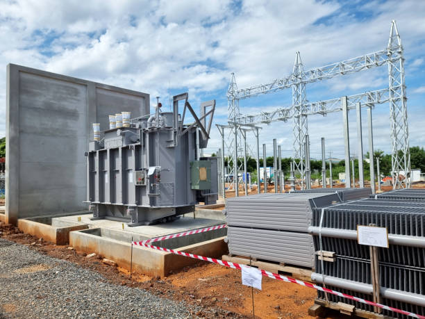
A zigzag earthing transformer is commonly connected to the relevant medium-voltage bus through appropriately rated switchgear and protective equipment. Its neutral terminal is then connected to the grounding system, either directly or through a specified grounding impedance.
The preferred connection point depends on the substation single-line diagram, the location of the main step-up transformer, and the desired grounding coverage. Engineers must establish whether the grounding transformer is intended to serve the entire collection network or a particular bus section.
Where bus couplers, sectionalizers, or multiple transformers are present, each switching configuration should be reviewed to determine whether the grounding source remains connected to the energized section.
The winding connections of the main power transformer strongly influence the need for a separate grounding transformer. A grounded-wye winding may already provide an appropriate grounding source, while a delta-connected or otherwise isolated winding may not provide an accessible neutral for the network in question.
The presence of a zigzag transformer should therefore be justified through a grounding study rather than assumed to be necessary at every renewable substation.
Engineers should examine the existing neutral paths, zero-sequence impedance, and the possibility of multiple grounding sources operating in parallel. These factors affect both fault-current magnitude and the behavior of protective relays.
The electrical rating of a zigzag earthing transformer is determined primarily by its grounding duty, not simply by the megawatt capacity of the renewable energy plant.
The grounding study should define the maximum ground-fault current that the network must accommodate or intentionally limit. This assessment considers system voltage, source impedance, transformer connections, cable capacitance, grounding resistance, and protection-clearing time.
For a resistance-grounded arrangement, a simplified initial estimate is:
Ig≈VLNRgI_g \approx \frac{V_{LN}}{R_g}
Here, IgI_g represents the intended ground-fault current, VLNV_{LN} is the applicable line-to-neutral voltage, and RgR_g is the grounding resistance. This approximation assumes resistance dominates the grounding path; the final calculation must include relevant transformer and network impedances.
Many zigzag earthing transformers are designed to carry ground-fault current for a specified short duration. The equipment must withstand the current until the protection system clears the fault.
The specified duty should align with the actual relay and circuit-breaker operating times, including backup protection. Engineers should also check the thermal and mechanical withstand capabilities of the transformer, neutral resistor, conductors, and associated switchgear.
Where continuous neutral current or auxiliary loads are expected, those requirements must be specified separately rather than relying exclusively on a short-time rating.
Zero-sequence impedance directly influences the available ground-fault current. If the impedance is too low, fault current may exceed equipment limits. If it is too high, the resulting current may be insufficient for dependable operation of certain protection schemes.
The design must balance current limitation with fault-detection sensitivity. Calculations should cover maximum and minimum fault conditions, relevant network configurations, and the tolerances specified for the equipment.
A zigzag earthing transformer is one element of a wider protection system. Its effectiveness depends on how well it integrates with relays, current transformers, voltage transformers, circuit breakers, and the facility’s overall earthing design. Meta Power Solutions emphasizes the importance of proper system integration and reliable grounding practices to support electrical safety and operational stability.
Protection engineers should determine which current-based or voltage-based methods are appropriate for the network. Depending on the configuration, ground-fault protection may use neutral-current measurements, residual current sensing, or voltage measurements associated with system displacement.
Relay settings must be sensitive enough to identify relevant faults while remaining stable during normal operation and switching events. In inverter-based systems, the limited and controlled fault-current response of power electronic equipment makes detailed protection studies particularly important.
During a single-line-to-ground fault, the voltages of healthy phases relative to earth can rise, particularly in networks that are inadequately grounded. These conditions can increase insulation stress and affect connected equipment.
The grounding transformer, grounding resistor, surge protection, and insulation coordination must therefore be evaluated as parts of a single design. Engineers should also assess cable capacitance and the potential for intermittent arcing ground faults where relevant.
A sound electrical design must be supported by appropriate installation practices and documented testing. Renewable substations often operate in exposed environments, making equipment condition and accessibility important throughout the service life.
The selected transformer should be suitable for the site’s ambient temperature, humidity, dust, pollution, and enclosure requirements. Coastal wind farms and solar installations in dusty regions may require additional attention to corrosion protection, terminal condition, and enclosure integrity.
The layout should provide adequate electrical clearances, safe access, suitable cable routing, and a reliable connection to the substation earth grid. Neutral conductors and grounding resistors must be rated for the specified fault-current duty.
Before energization, commissioning teams should verify winding connections, nameplate ratings, insulation condition, grounding continuity, and the correct operation of associated protective equipment.
The grounding resistor, where fitted, should be checked against its specified resistance and thermal duty. Relay testing should confirm that ground-fault signals produce the intended alarms and trips.
Periodic maintenance should follow the manufacturer’s instructions and the site’s maintenance plan. Any major change to inverter capacity, transformer connections, feeder topology, or protection settings should trigger a review of the grounding study.
Substation design should follow the electrical codes and standards applicable to the project’s jurisdiction and utility connection agreement. Relevant references may include IEC 60076-6 for reactors and associated transformer applications where applicable, IEEE 3003.1 for industrial and commercial system grounding, and the relevant interconnection standards for distributed energy resources.
The engineering team should verify the current editions, exact scope, and project-specific requirements before specifying compliance. Standards do not replace a site-specific grounding study.
Technical documentation should include the single-line diagram, grounding calculations, zero-sequence impedance data, grounding resistor specifications, protection settings, equipment ratings, factory test records, and commissioning results. Maintaining these records makes future upgrades and fault investigations more reliable.
Zigzag earthing transformers can play a valuable role in renewable energy substation design by establishing an artificial neutral, providing a defined zero-sequence current path, and supporting dependable ground-fault protection. Their applications extend across solar photovoltaic plants, wind farm collection networks, and battery energy storage facilities where the existing electrical configuration does not provide a suitable grounding reference.
Successful implementation depends on more than selecting a transformer with an appropriate voltage rating. Engineers must evaluate the main transformer connections, grounding philosophy, fault-current limits, zero-sequence impedance, inverter behavior, relay coordination, and expected network switching conditions.
When these factors are addressed during the design stage and reinforced through proper commissioning and maintenance, zigzag earthing transformers can contribute to safer, more predictable, and more reliable renewable energy substations. A carefully engineered grounding arrangement helps protect electrical infrastructure while supporting the dependable integration of renewable generation into modern power networks.